Starting the plant…

Industrial Training Models

The mining plant,
on your lab bench.

Training models that really work: they crush, convey, grind and float with real mechanics, sensors, HMI and automatic control. Designed for universities, technical institutes and training centers.

4models in development
24 VSELV safety
ModbusPLC-ready
SCROLL
From ore to concentrate

A concentrator plant circuit, module by module

Each model reproduces a real stage of mineral processing. Together they form the complete line: size reduction, liberation and separation. Click a stage to go to its model.

ROM · minaMineral 01 · JC-01Chancado mandíbula de 4 barrasroca 22 mm → 5–15 mm 02 · CV-01Correas pesómetro + PI60 kg/h · 14° 03 · BM-01Molienda cascada + catarata80 rpm · 69 % Nc 04 · FL-01Flotación 4 celdas · aire realnivel PI · trazador Concentradorebalse Colas → MP-01espesador · próximamente
Ore / solidsSlurry / waterIn development
01
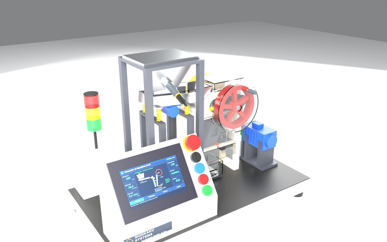
Primary crushing · JC-01

Jaw crusher

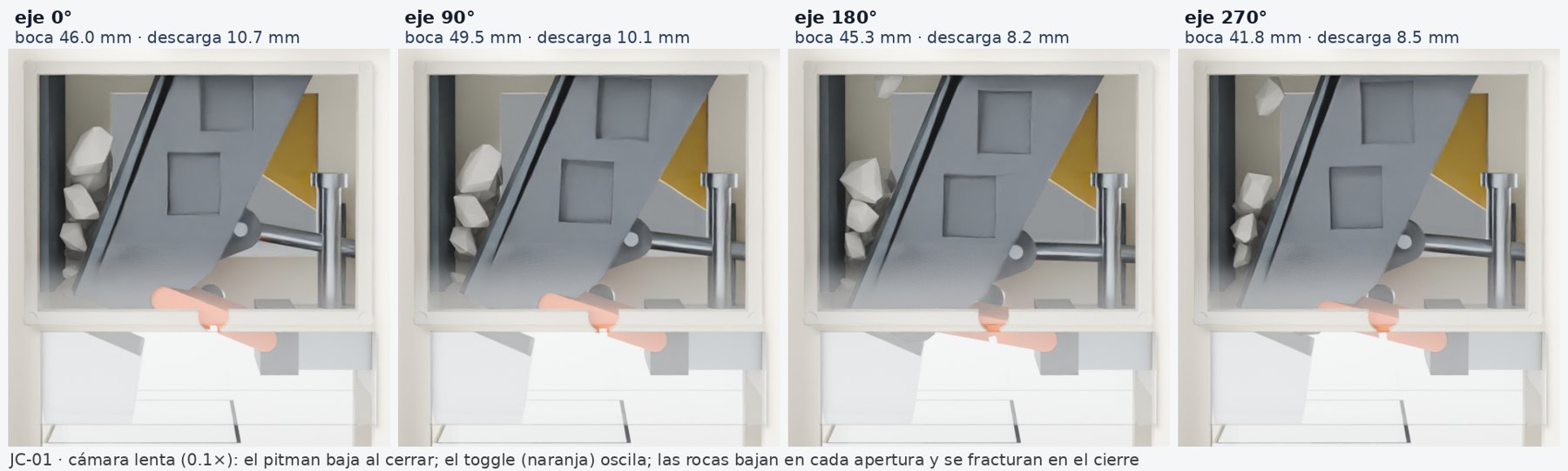
A real four-bar mechanism (eccentric + pitman + toggle) crushes real rocks. The simulation uses exactly the same kinematics as the CAD.

Design approved · prototype in development
3D VIEWER · JC-01
drag · zoom · tap the points

Controls

Live reading

—

Data sheet

24 V DC motor · 100 WEccentric e = 5 mmCSS 5–15 mmFuse toggle 2.2 kNFlywheel Ø130Load cell7" HMI + ESP32

Real process

The primary crusher receives ore from the mine (up to 1–1.5 m) and reduces it to ~150–250 mm. The moving jaw approaches and moves away from the fixed jaw; the rock breaks by compression and falls by gravity as soon as it fits through the opening.

What the model simulates

  • Real elliptical motion of the jaw (four-bar linkage).
  • Choke feeding with a controlled vibrating tray.
  • CSS setting and its effect on product size.
  • Mechanical fuse (toggle) and safe stop.

What students learn

  • Reduction ratio and particle size curve.
  • Power vs. feed: feeder control loop.
  • Interlocks, sequential start and alarms.
  • Mass balance with a load cell.
02
Conveying · CV-01

Belt conveyor system

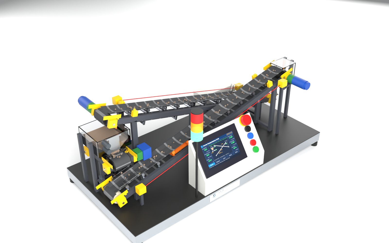
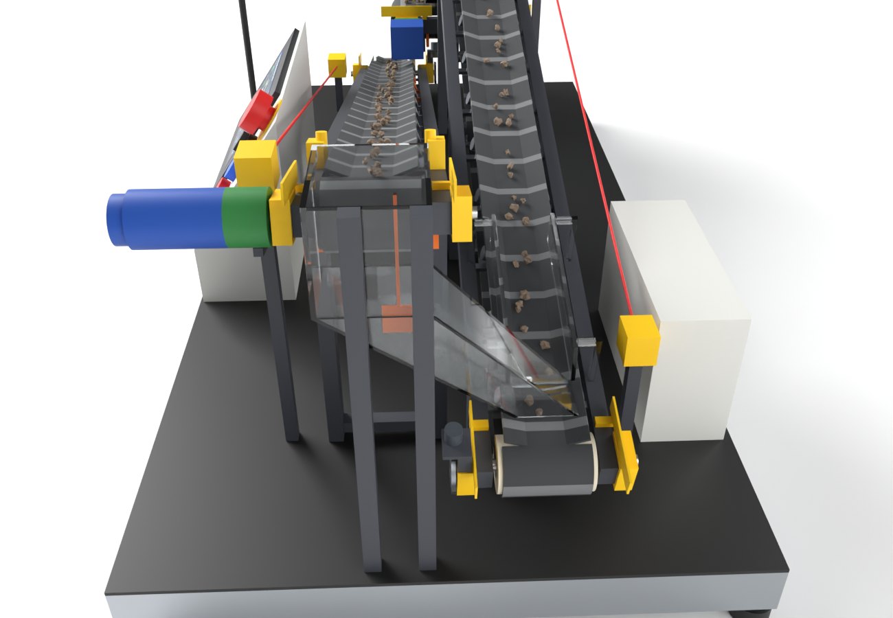
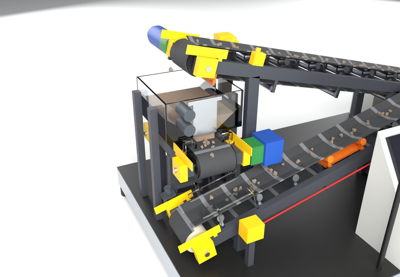
A closed circuit of three belts with real gravel: the feeder doses from the hopper, the main belt weighs the material in line and a chute transfers it to the return belt. Pull the pull-cord and watch everything stop.

Design under review
3D VIEWER · CV-01
drag · zoom · tap the points

Controls

Live reading

—

Data sheet

3 belts 60 mm, 20° troughing14° incline · 0.1 m/sBelt scale WT-102PI flow loop39° chutePull-cord · zero speed7" HMI + ESP32

Real process

Belt conveyors link the stages of a plant: they carry crushed ore to the stockpiles and to the mill. Flow is measured with a belt scale and controlled with the feeder speed; conveyors start from downstream to upstream and have protection devices along their whole length.

What the model simulates

  • Closed circuit: the material returns to the hopper and never runs out.
  • Start-up pre-alarm, cascade interlocks and orderly shutdown.
  • Belt scale with real transport dead time.
  • Pull-cord, zero speed, misalignment and blocked chute.

What students learn

  • Flow loop with dead time: PI tuning.
  • Belt scale calibration, tare and totalizer.
  • Sequences and interlocks between machines.
  • Conveyor calculation: capacity, power and belt tensions.
03
Grinding · BM-01

Ball mill

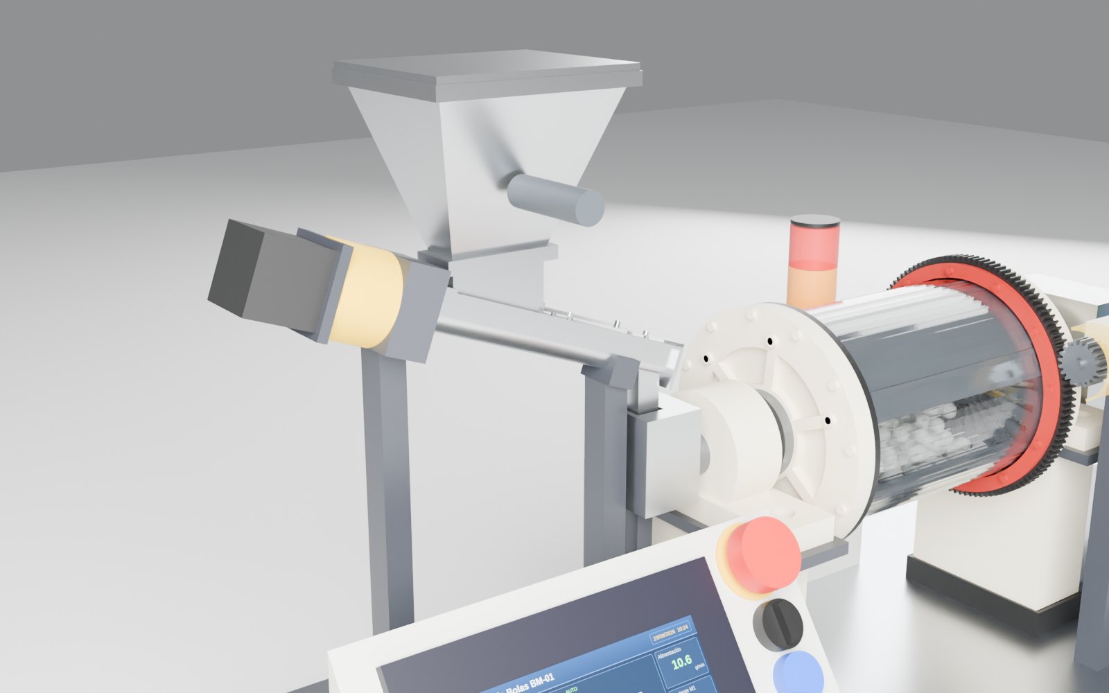
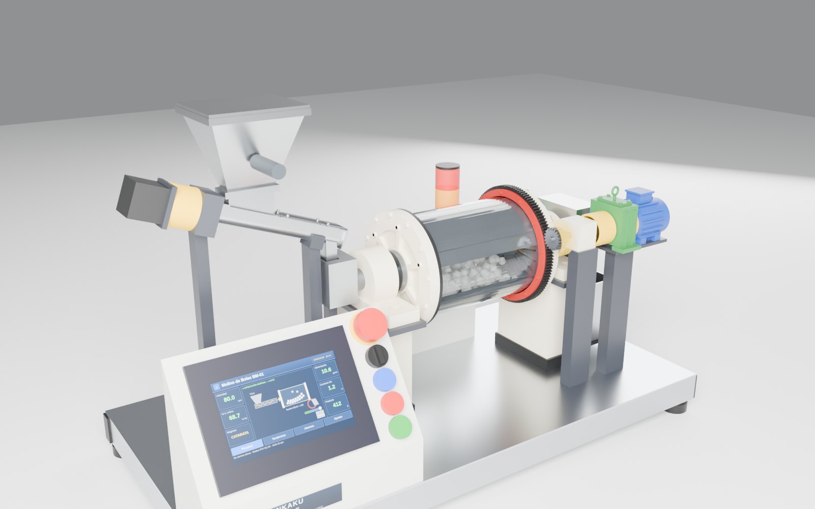
Transparent drum with 650 balls, real girth gear and pinion and a screw feeder. Change the speed and watch the charge go from cascading to cataracting and centrifuging.

Design frozen · prototype in development
3D VIEWER · BM-01
drag · zoom · tap the points

Controls

Live reading

—

Data sheet

PMMA drum Ø150 × 200650 POM balls Ø12Nc = 116 rpmGear z120 · pinion z20 m1.5Total ratio 30:1Screw 1.8–28 g/min7" HMI + ESP32

Real process

The ball mill reduces the crushed product to less than ~0.2 mm to liberate the valuable mineral particles. The steel balls ride up the drum wall and fall onto the charge: impact and abrasion.

What the model simulates

  • Charge regime as a function of % critical speed (Nc = 42.3/√D).
  • Real drive train: motor → gearbox → pinion → girth gear.
  • Continuous dosing with a screw and discharge through a grate.
  • Start-up pre-alarm, ramps and interlocked guards.

What students learn

  • Critical speed and take-off point: cos ψ = ω²r/g.
  • Gear design and grinding power.
  • Speed control with VFD/driver and HMI.
  • Residence time and mass balance.
04
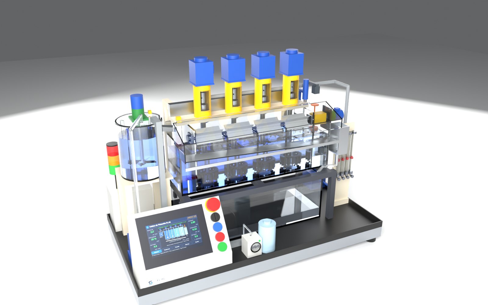
Flotation · FL-01

Flotation cell bank

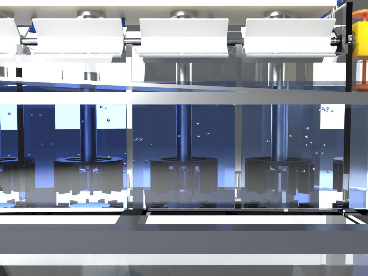
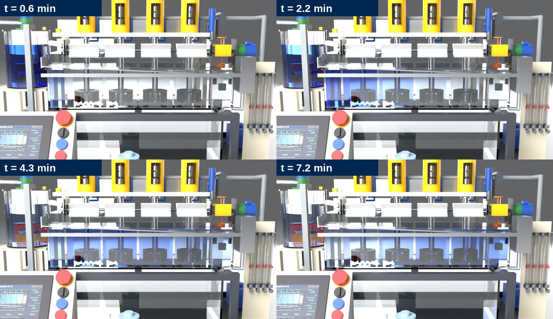
Four transparent cells that run on water only: spinning rotors, real air bubbles, level controlled by a PI with a dart valve and a dye pulse that travels through the bank.

Design under review
3D VIEWER · FL-01
drag · zoom · tap the points

Controls

Live reading

—

Data sheet

4 PMMA cells 100×120Rotor Ø46 · 900–1800 rpmAir 1–7 L/min/cellLIC-101 PI + dart valveColorimeter AT-101Closed circuit 12.5 LWater only

Real process

In flotation, air bubbles capture the valuable (hydrophobic) mineral particles and carry them into the froth, which overflows as concentrate. The tailings pass from cell to cell. Pulp level is the main control variable.

What the model simulates

  • Real hydraulics of the bank: overflow, tailings and dart valve.
  • Air hold-up: the water rises as the air increases.
  • Tanks in series with a dye tracer (RTD curve).
  • No reagents or froth: clean and safe for the classroom.

What students learn

  • Level control of an integrating process (PI tuning).
  • Residence time τ = V/Q and perfect mixing.
  • Instrumentation: float, laser, rotameters, colorimeter.
  • Alarms, cover interlocks and emergency stop.
Common platform

Real engineering, at classroom scale

All models share the same architecture: learn it once and apply it across the whole line.

Real mechanics

Real bearings, shafts, calculated gears and couplings. Parametric CAD, verified zero interferences and 3D-printed parts.

Control and HMI

ESP32 + 7" touch HMI: manual and automatic modes, sequences, alarms and interlocks. Modbus RTU/TCP to connect a Mitsubishi, Siemens or other PLC.

Safety first

24 V DC SELV, interlocked guards, dual-channel emergency stop, beacon and electronics outside the wet zone.

Digital twin

Each model has its own animated 3D model with the same physics as the equipment: for remote classes, lab preparation and this website.

Engineering renders

Gallery

Images rendered directly from the CAD model of each training model.
Roadmap

Upcoming models

LT-01

Tank level control

Coupled tanks, PID loops and cascade tuning.

CP-01

Chemical process trainer

Dosing, pH, temperature and in-line mixing.

MP-01

Complete modular plant

Thickener and the integrated line with SCADA.

Does your institution need a process laboratory?

Custom training models, training and teaching materials in Spanish, English and Japanese.

Request information →